How do Fiber Optic Cables Really Work?
If you are like me, you learned that light travels in a straight line. So why, when I use plastic, or for that matter glass, I can make light travel around corners to where ever I like?
Refraction in Fiber Optic Cables
The answer lies in refraction. This what happens when light goes from one density of material to another. What happens is the light actually changes speed in different densities of material. Again, this may seem strange, but what we were taught at school was that the speed of light in a vacuum is a constant. What was not stressed was that in substances such as water, glass, plastic, light actually travels at different speeds, which are slower than that in a vacuum. As light takes the shortest path through a substance, this results in the bending of light as it goes from a material of one different optical density to another. relates. This is called ‘refraction’. To go into the detailed physics of this is beyond the scope of this article.
A helpful term is ‘Refractive Index’ (RI). It is a measure of the change in speed of the light, although we often think of it as describing the density of the material the light is going through. So a vacuum has an RI of 1.0, whereas that of water is 1.3, which is why we get odd effects when looking into water or from water into air. For example, you and I have experienced this so called refraction when looking into water. We look down and see an object that appears to be higher up in the water than it really is (see image below):

Let’s do a thought experiment, that you may have done in reality. Suppose you are under water and are looking up at the surface, the inverse of the above image. If you are a fish, and intentionally look up at the eye, will be able to see reasonably clearly, although as noted above, the light is bent and the eye is not really you as a fish think it is. If you lower your fishey gaze, so that you are looking more obliquely up at the surface, you will eventually get to a point where the surface takes on a black oily look and you can no longer see above the water. The angle at which this occurs is called the ‘critical angle’. What is happening is the light is traveling along the water and then is reflected down bends down to reach your eye. But let’s keep going beyond this critical angle. You now start to see the fish swimming near to but below you! What’s happened? The light is no longer bending as it goes into the air, but rather is being reflected off the surface of the water. We call this total internal reflection, so the surface is acting like a mirror.
The diagram below provides an example of this where the green line reflects the fish looking up to a person above the water, the red line is when the critical angle is reached, and the blue line is when total internal reflection occurs.

So, what has this to do with fiber optics? Plastic or glass fibers have a fairly high RI of about 1.5. Hence, as you shine light down a plastic fiber, if the angle the light subtends to the surface of that fiber is less than the critical angle, then the light will bounce off the internal surface of the fiber and carry on down the fiber, bouncing back and forward. If the angle of the light is too large, then the light will ‘leak’ out of the fiber and be lost into the air. This is how fiber optics ‘capture’ the light inside the fiber. Providing the fiber is reasonably straight, the light will remain inside the fiber. Of course, fibers are used to take light around corners, which raises the question, how much of a bend will a fiber withstand before substantial amounts of light will leak out of it. This leads to a discussion of the ‘Maximum Bend Radius’.
Maximum Bend Radius in a Fiber Optic Cable
The question is, how steep a corner can the light be bent around? There must be some limit - and yes there is. As one bends a fiber light starts to leak out as the bend exceeds a critical level. It’s rather like taking the above diagram and tilting the right half down. The further that is tilted the blue line on the left half will eventually become the red line on the right half and eventually the green one. There is a rule of thumb.

It is that the bend radius should be greater than 10 times the fiber diameter, which we will call the Bend Radius Ratio. This is used as a guide in all glass fiber optic communication applications in which the wavelengths of light are in the infrared - i.e. wavelengths in the 1,300nm range. So does this need to be modified for much shorter wavelengths in the visible 500nm range? Published papers reveal that there is quite a strong wavelength dependency in the infrared range, however, there is nothing published for the visible range (see: Unger, C., and Stöcklein, W., “Investigation of the Microbending Sensitivity of Fibers”, Journal of Lightwave Technology, Vol. 1, No. 4, April 1994.)
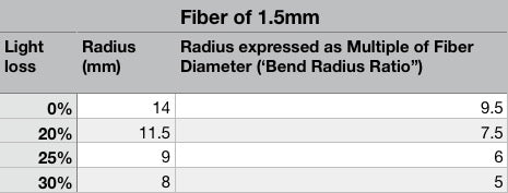
Using the ‘rule of thumb’ would mean that for a 1mm fiber the maximum bend radius should be 10mm, or just under 1/2”, and for a 1.5cm fiber it should be 15mm just over 1/2”. My experimentation (see table below) reveals that for a 1.5mm fiber, there is minimal light loss for a bend radius of about 14mm, and about 11.5mm there is a 20% light loss, resulting in a Bend Ratio of 7.5, considerably less than the rule of thumb used in the communication industry. Incidentally, a light loss of 20% is difficult to perceive.
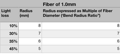
Likewise, for a 1mm fiber the figures are:
|
So the Bend Radius Ratio for the 1mm fiber that results in a 20% loss will be somewhere around 7.5, the same as for the 1.5mm fiber. |
In summary, if one is willing to accept a 20% light loss, the maximum Bend Radius for the 1.5mm fiber is 11.5mm (as against the proposed 15mm, using the typical ‘rule of thumb’) and for the 1.0mm fiber it is 7.5mm (as against the rule of thumb of 10mm).
Connecting Fiber Optics
There are times when one needs to connect fibers together. Indeed, if you worked in the data communication business using microwave light, you would know that connecting fibers is a major topic in order to minimize communication loss. The topic comes up in hobbies when working with modular systems that need to be set up and taken down, or when connecting from a single large fiber to a bundle of smaller ones, for example when providing lighting to a car (headlights, tail lights, interior) or to a tree - a larger fiber may be used to provide the light to multiple small fibers close to the object being lit. However, how critical is connecting for a hobby using visible light?
There are a number of factors to be considered in reducing light loss and thereby providing optimal connecting of fibers. Most come down to how clean a cut has been made to the fiber end, how close the fibers are to one another and finally, and most importantly, reducing the impact of changes in refractive index in a fiber / air /fiber connection. Hence, in data communication technology, it is very important to polish the ends of fibers, having connectors that hold them in close proximity to each other and using something called an ‘index matching’ fluid to reduce the refractive index issue. Do we need to consider all these things with plastic fiber optics? Fortunately, the answer is, it depends.
Flat polishing can give you a 4% reduction in back reflection (Tutorial: Fiber Optic Basics by Newport Corporation. https://www.newport.com/t/fiber-optic-basics ) As the eye cannot detect such a small change in intensity (the threshold is around 5%) polishing plastic fibers the least important factor and can be considered unnecessary.
Close connecting of fibers is always important. This can easily be achieved using various commercially available fiber connectors, or using home made solutions, such as inserting fibers into a tube with an ID close to that of the fiber being used.
However, ‘index matching’ is probably the most easily overlooked and yet the most important factor in minimizing the light loss. Once again, importance depends on the application. If the intent is to use the fiber optics to only allow the eye to see there is a light, such as providing lights from a train engine, or headlights on a car, then index matching may not provide much benefit. On the other hand, if the intent is to illuminate an object, then one wants to retain as much light as possible and hence index matching will be important.
What is Index Matching?
Index matching attempts to remove the problem of an air gap, usually by filling the gap with a fluid. As noted above, the whole reason that fiber optics is such a good conductor of light is the difference in the refractive index of the fiber compared to its surroundings. It is this that keeps the light inside the fiber. So when the light reaches the end of a fiber where there is an air interface, there is a mismatch of refractive index and a significant amount of the light will be reflected back from the fiber end. If a substance that has the same or very close refractive index is used to connect the fibers, then the loss will be minimized. The typical plastic used in a plastic fiber is PMMA and has a refractive index of 1.5. So selecting a connecting fluid that has a similar refractive index and is optically clear will be a good candidate as an index matching fluid.
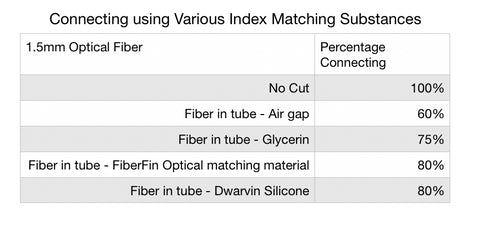
The following are the results conducted by the author using various connecting methods.
A 1.5mm fiber was cut with a sharp knife, providing a clean cut. A short 1” (2.5cm) piece of aluminum tubing (K&S #8101) was then used to close connect the fibers. In the various experiments different fluids were then put onto the ends of the fibers prior to their insertion into the tube.
As can be seen, the use of an index matching material significantly improves the connecting between the cut fibers.
Some practical comments are in order here.
- Glycerin is inexpensive and readily available. However, it is very slippery which makes it a bit more difficult to hold the fibers inside a simple tube, but if a product that is specifically designed to hold the fibers together inside a tube, it can be a very good solution.
- Various different commercial index matching materials are available, as in the example of the FiberFin product listed above, but these tend to be expensive for the average hobbyist, although FiberFin’s is the least expensive but prices can range as high as $75 for 1ml. Most of these are an optically clear silicone material and specifically designed for data communication applications.
- Dwarvin has a specially selected silicone material that is well suited to the optical range and delivers the same results as that of other index matching materials on the market but has an element of stickiness that helps hold the fibers inside a tube.
So, by taking care in cutting the fiber, using a sleeve to hold the fibers in proximity with each other, and selecting a suitable Index matching fluid, one can readily provide a connecting solution that will meet the needs of those mentioned above, particularly those who work with modular layouts.